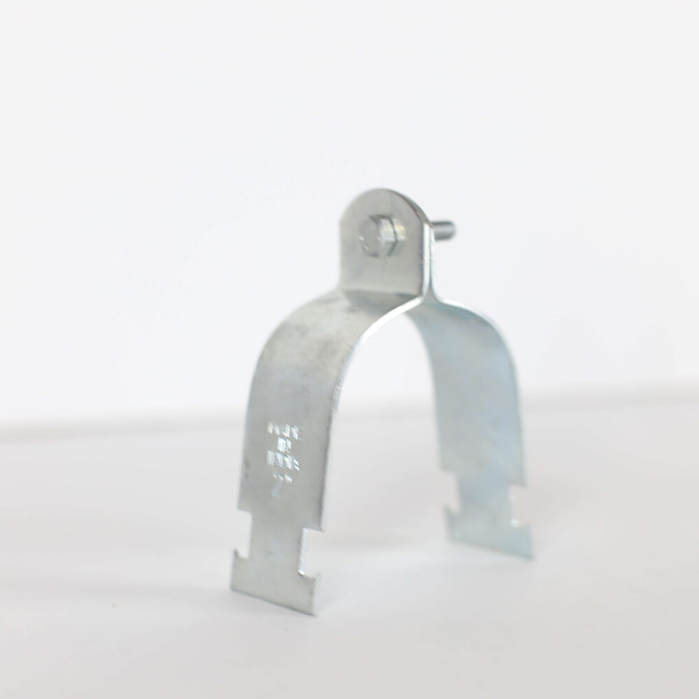
Product Designation System
NAC-TPCC-XX | NAC = New Age Corporation | TPCC = Two Piece Channel Clip | XX = Nominal pipe size (imperial)
Complete Technical Specifications
| Specification | Details | Specification | Details |
| Material (Clamp) | Mild Steel (ES 138 / A36) | Construction | Two-piece bolted assembly |
| Pipe Size Range | DN15 to DN100 (½” to 4″) | Movement Type | Axial (longitudinal) sliding |
| Finish Options | Electro-Galv / Hot-Dip / Pre-Galv / Plain | Operating Temp | -20°C to +150°C |
| Channel Compatibility | 41×41mm, 41×82mm strut channels | Fastener Included | M6×25, M8×40 (size dependent) |
| Installation Method | Bolted to channel – no welding | Guidance Function | Prevents lateral movement only |
| Load Type | Guide only (not load-bearing riser support) | Standards | Egyptian Code / MSS SP-58 |
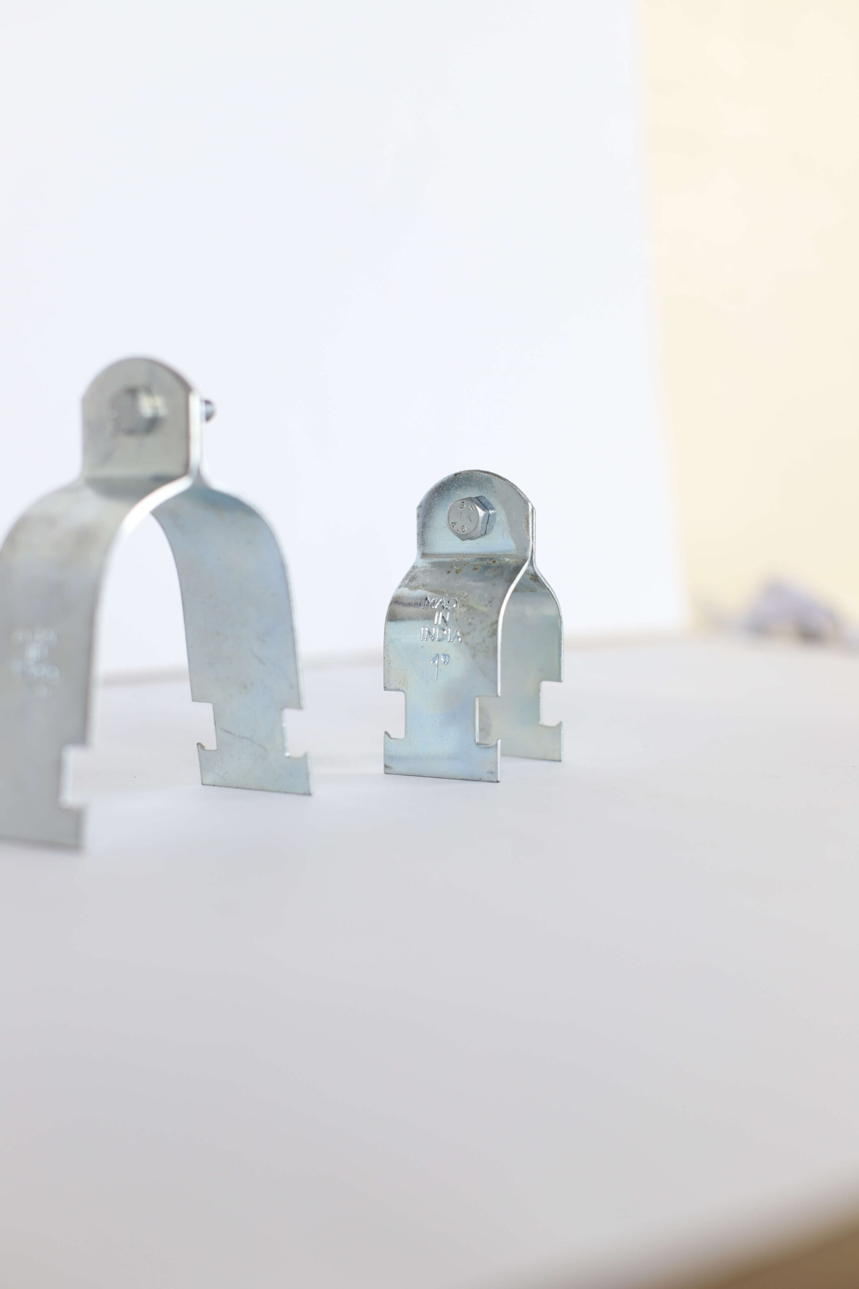
Product Range & Dimensional Specifications
| Product Code | Nominal Pipe Size | Pipe OD (mm) | Dimension A (mm) | Dimension B (mm) | Dimension C (mm) | Fastener Size |
| NAC-TPCC 22 | ½” (DN15) | 15–22 | 50.5 | 14.2 | 25.00 | M6 × 25 |
| NAC-TPCC 27 | ¾” (DN20) | 20–27 | 57.1 | 17.5 | 30.00 | M6 × 25 |
| NAC-TPCC 34 | 1″ (DN25) | 25–34 | 63.8 | 20.6 | 38.00 | M6 × 25 |
| NAC-TPCC 42 | 1¼” (DN32) | 32–42 | 76.2 | 25.4 | 46.00 | M6 × 25 |
| NAC-TPCC 48 | 1½” (DN40) | 40–48 | 81.5 | 28.4 | 52.00 | M6 × 25 |
| NAC-TPCC 60 | 2″ (DN50) | 50–60 | 95.8 | 34.8 | 65.00 | M8 × 40 |
| NAC-TPCC 73 | 2½” (DN65) | 65–73 | 108.7 | 41.1 | 78.00 | M8 × 40 |
| NAC-TPCC 89 | 3″ (DN80) | 80–89 | 128.3 | 50.8 | 94.00 | M8 × 40 |
| NAC-TPCC 114 | 4″ (DN100) | 100–114 | 153.7 | 63.5 | 120.00 | M8 × 40 |
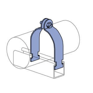
Dimensional Reference
- A: Total height from channel base to top of clamp
- B: Clamp width (lateral dimension)
- C: Clamp depth (fore-aft dimension perpendicular to pipe axis)
Note: Dimensions allow for pipe OD variation due to different schedules (Schedule 10, 40, 80) and insulation thickness. Verify actual pipe OD before ordering.
Material & Finish Specifications
| Finish Type | Coating Specification | Recommended Application |
| Electro-Galvanized (EG) | 12–25 μm per ASTM B633 | Indoor mechanical corridors, dry environments |
| Hot-Dip Galvanized (HDG) | ≥55 μm per ASTM A153 | Outdoor pipe racks, coastal zones, high-humidity areas |
| Pre-Galvanized (PG) | Standard mill coating per ASTM A653 | General construction, moderate indoor conditions |
| Plain (Uncoated) | No coating | Paint-ready installations or controlled environments |
Pipe Guidance Application
Primary Function: Guided Movement
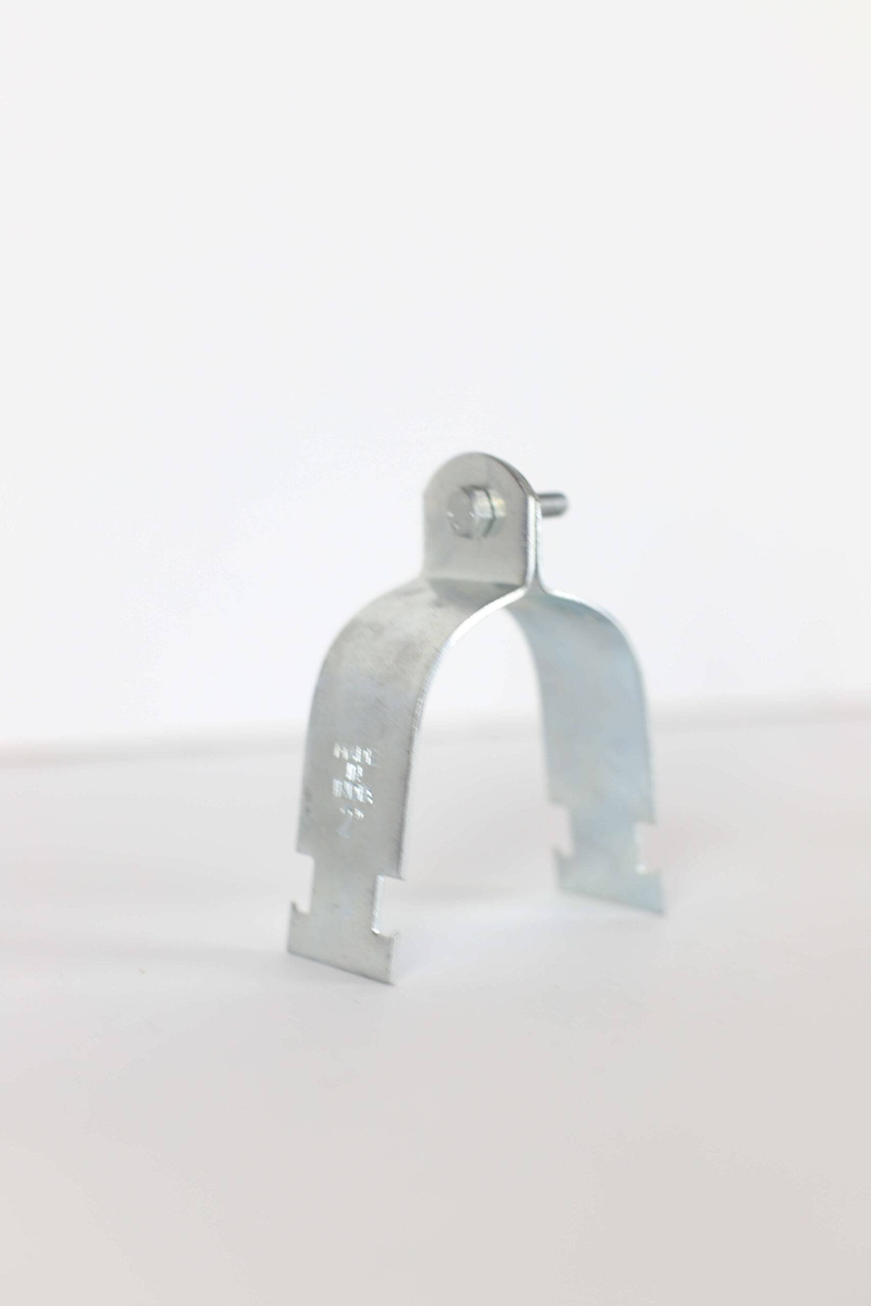
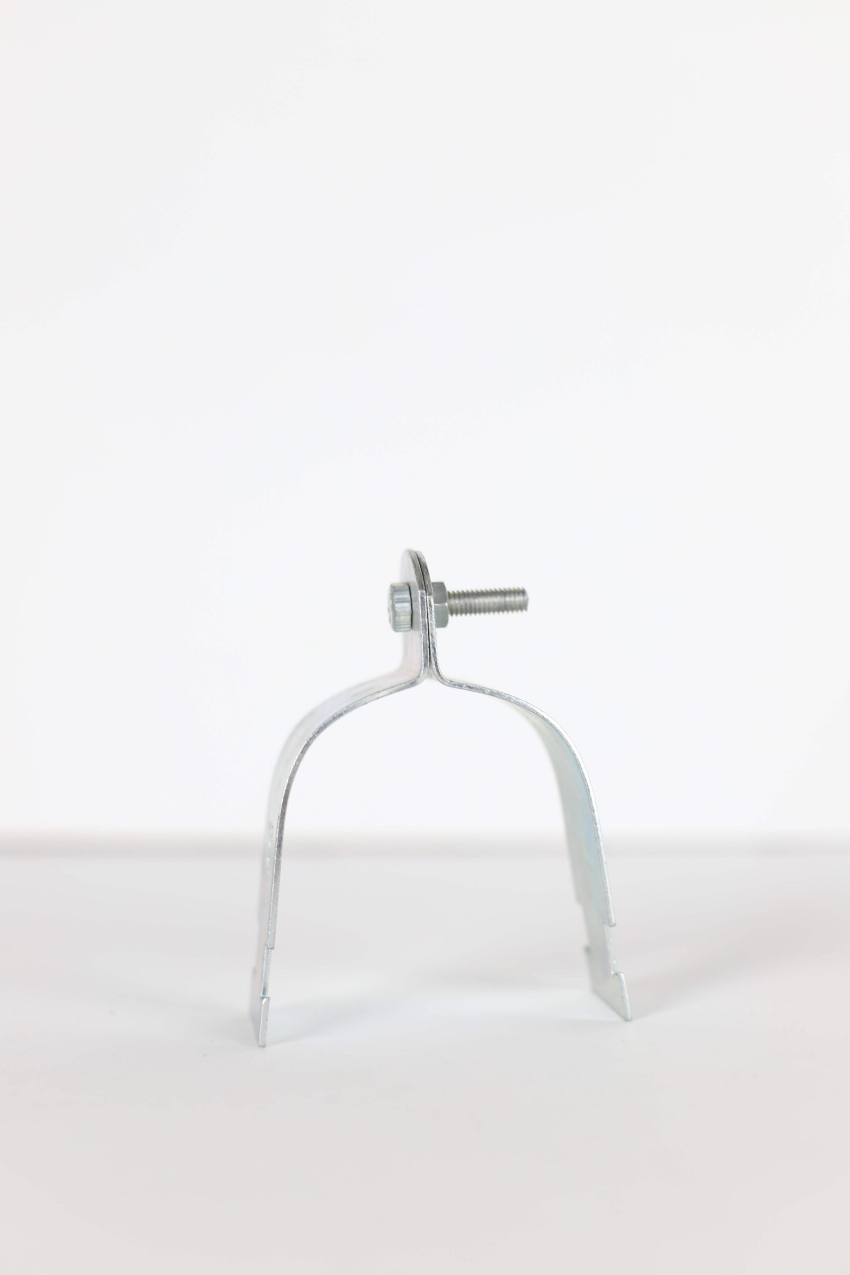
The Strut Clamp – Two Piece Channel Clip performs a specific and critical function in piping systems:
What It DOES:
- ✓ Guides pipe along strut channel path (prevents lateral/vertical displacement)
- ✓ Allows controlled axial (longitudinal) movement for thermal expansion/contraction
- ✓ Maintains pipe alignment through temperature cycles
- ✓ Prevents pipe from lifting off or falling out of support structure
- ✓ Distributes lateral loads (wind, seismic) to strut channel framework
What It DOES NOT Do:
- ✗ Does NOT carry vertical dead weight (use riser clamps or pipe hangers for load bearing)
- ✗ Does NOT provide vibration isolation (use EPDM-lined hangers for acoustic control)
- ✗ Does NOT act as a rigid anchor (use anchor supports to restrain expansion)
Typical Installation Locations
- Long horizontal pipe runs on strut channel racks (>10m) subject to temperature change
- HVAC chilled water and hot water distribution corridors
- Fire protection system loops with temperature variations
- Roof piping support frames exposed to weather
- Industrial process piping with thermal cycling
- Mechanical tunnels and underground utility corridors
Critical Design Distinction: Guide vs. Anchor
In a properly designed piping system with thermal expansion:
| Component | Function | Location | Movement |
| Anchor | Restrains pipe in all directions | Fixed points (equipment, turns) | Zero movement |
| Guide | Allows axial movement only | Between anchors | Slides longitudinally |
| Support | Carries vertical load | Throughout run | May allow movement |
The Strut Clamp – Two Piece Channel Clip is a GUIDE. It must be used in combination with proper anchors and load-bearing supports per mechanical design calculations.
Application Selection Guide
| System | Typical Use | Recommended Sizes | Finish | Spacing |
| HVAC Chilled Water | Corridor distribution racks | DN40–DN100 | Hot-Dip Galvanized | 3–5m |
| HVAC Hot Water | Heating system mains | DN32–DN80 | Hot-Dip Galvanized | 3–5m |
| Fire Protection | Sprinkler loop distribution | DN50–DN100 | Hot-Dip Galvanized | Per NFPA 13 |
| Process Piping | Industrial plant piping | DN25–DN100 | Hot-Dip Galvanized | 4–6m |
| Utility Distribution | General service piping | DN25–DN50 | Electro-Galvanized | 3–5m |
| Roof Piping | Outdoor exposed runs | DN25–DN80 | Hot-Dip Galvanized | 3–4m |
Thermal Expansion Considerations
Why Guided Movement Matters
When a pipe heats or cools, it expands or contracts. For steel pipe, the thermal expansion coefficient is approximately 11.7 × 10⁻⁶ per °C.
Example Calculation:
- Pipe length: 50m
- Temperature change: 60°C (e.g., 20°C ambient to 80°C operating)
- Expansion: 50m × 11.7 × 10⁻⁶ × 60°C = 35mm movement
Without proper guides, this 35mm expansion can cause:
- Pipe to buckle or snake laterally
- Joints to leak at connections
- Supports to fail due to lateral forces
- Equipment nozzles to overstress
Solution: Place guided supports (like the Strut Clamp) between rigid anchors to direct expansion in a controlled direction.
Guide Spacing Guidelines
| Pipe Size | Recommended Guide Spacing | Typical Between Anchors |
| DN15–DN25 | 3–4m | 15–20m |
| DN32–DN50 | 4–5m | 20–30m |
| DN65–DN100 | 5–6m | 30–40m |
Note: First guide should be placed close to anchor (typically 1–2m away) to establish direction of movement.
Installation Requirements
Pre-Installation Planning
System Design Verification:
- Confirm piping system has been analyzed for thermal expansion per ASME B31.1 or B31.3
- Identify anchor locations on mechanical drawings
- Verify guide spacing between anchors per design calculations
- Ensure strut channel framework is adequately braced for lateral loads
Component Selection:
- Select clamp size based on actual pipe OD (including insulation if applicable)
- Verify strut channel size (41×41mm or 41×82mm) matches clamp design
- Confirm channel anchors are adequate for lateral guide forces
- Choose finish based on environmental exposure (HDG for outdoor)
Installation Procedure
- Install and verify strut channel framework
Ensure strut channels are level and properly anchored
Verify channel is aligned along pipe run direction
Check that channel anchors are torqued per structural specifications
- Position lower half of clamp in channel
Insert lower clamp piece into strut channel slot
Position at designed location per piping drawings
Ensure clamp seats fully in channel profile
- Place pipe into clamp
Lift pipe and position in lower clamp cradle
Verify pipe is centered in clamp – not offset to one side
Confirm adequate clearance for axial movement (pipe should not bind)
- Install upper clamp piece
Position upper clamp half around pipe
Align bolt holes between upper and lower clamp pieces
Insert fasteners (M6×25 or M8×40 depending on size)
- Tighten clamp – CRITICAL: Do not over-tighten
Tighten bolts gradually in stages, alternating sides
Recommended torque:
- M6×25: 8–10 Nm
- M8×40: 15–18 Nm
CRITICAL: Clamp should hold pipe snugly but allow sliding movement when pipe expands
Test: With hand pressure, verify pipe can slide axially through clamp (should require moderate force)
- Verify movement clearance before insulation
Manually slide pipe back and forth to confirm free axial movement
Check that no obstructions prevent expansion/contraction
If insulation will be added, verify clamp still allows movement with insulation in place
- Final system check
Verify all guides are aligned along pipe run
Confirm anchors are properly restrained
Check that first guide near anchor is positioned correctly
Perform visual inspection of entire support system
Installation Best Practices
✓ Install guides working from anchor outward along expansion direction
✓ Maintain consistent clamp orientation throughout run
✓ Use lock washers or lock nuts on all fasteners
✓ Mark pipe with paint stripe to monitor expansion movement during startup
✓ Avoid installing guides too tight – pipe must slide freely
System Design Example
Typical HVAC Chilled Water Pipe Rack
Scenario:
- Pipe: DN80 (3″), 40m long horizontal run
- Temperature: 7°C chilled water (ambient: 30°C)
- Strut channel: 41×82mm, 2.5mm thick
Support Strategy:
- Anchors: Fixed anchors at both ends (at equipment connections)
- Load Supports: Pipe hangers every 3.5m to carry vertical weight (8 total)
- Guides: Strut clamps (NAC-TPCC 89) every 5m to guide expansion (7 total)
Thermal Expansion:
- ΔT = 30°C – 7°C = 23°C
- Expansion = 40m × 11.7 × 10⁻⁶ × 23°C = 10.7mm
- With anchors at both ends, pipe expands 5.4mm toward each anchor
Guide Placement:
- First guide: 2m from left anchor
- Subsequent guides: 5m spacing
- Last guide: 2m from right anchor
This configuration allows controlled expansion while preventing lateral buckling.
Why Specify New Age Strut Clamps – Two Piece Channel Clip?
| Advantage | Benefit to Your Project |
| Allows Controlled Axial Movement | Prevents pipe stress, cracking, and joint failure during temperature changes |
| Modular Strut Channel Integration | Zero field welding – fast installation, easy field adjustments |
| Precise Sliding Tolerance | Factory-set clearance ensures reliable movement without binding |
| Multiple Finish Options | Suitable for indoor, outdoor, and industrial environments |
| Standard Thickness Control | Consistent clamping force across all units – no field variations |
| 100% Egyptian Manufacturing | 3–7 day delivery (Cairo/Giza), competitive pricing, local technical support |
| Universal Channel Compatibility | Works with all standard strut channel systems (not proprietary) |
Product Comparison: Support Types
| Feature | Strut Clamp (Guide) | Pipe Hanger | Riser Clamp | Half Saddle | |—|—|—|—| | Primary Function | Guides movement | Carries load (suspended) | Carries load (vertical) | Supports on wall | | Vertical Load Capacity | Minimal (guide only) | High (460–1,200 kg) | High (750–5,800 kg) | Moderate (35–350 kg) | | Axial Movement | ✓ Allows sliding | ✗ Rigid | ✗ Rigid | ✗ Rigid | | Mounting | Strut channel | Threaded rod/ceiling | Floor/beam | Wall | | Typical Spacing | 3–6m | 2.5–4m | Per floor | 1.5–3m | | Use With | Anchors + load supports | Ceiling structure | Structural floors | Vertical walls |
Common Installation Mistakes to Avoid
Mistake #1: Using Guides as Load-Bearing Supports
❌ Wrong: Installing only strut clamps to support pipe weight
✓ Correct: Use pipe hangers or other load-bearing supports to carry weight; strut clamps guide only
Mistake #2: Over-Tightening Clamps
❌ Wrong: Tightening clamps until pipe cannot move at all
✓ Correct: Tighten to recommended torque; pipe should slide with moderate hand pressure
Mistake #3: Insufficient Guide Spacing
❌ Wrong: Placing guides too far apart (>8m), allowing pipe to buckle laterally
✓ Correct: Follow spacing guidelines (3–6m depending on pipe size)
Mistake #4: No Anchors in System
❌ Wrong: Using all guides with no fixed anchors – pipe “walks” along run
✓ Correct: Install fixed anchors at ends and direction changes; use guides between anchors
Mistake #5: First Guide Too Far from Anchor
❌ Wrong: First guide >5m from anchor – pipe may buckle near anchor
✓ Correct: Place first guide 1–2m from anchor to establish expansion direction
Standards & Certifications
- ✓ Egyptian Mechanical Code – Pipe guidance, thermal expansion accommodation, support spacing
- ✓ ASME B31.1 – Power piping thermal expansion design (reference standard)
- ✓ ASME B31.3 – Process piping thermal expansion design (reference standard)
- ✓ MSS SP-58 – Pipe support classification (guide category)
- ✓ ASTM B633 – Electro-Galvanized coating specification (12–25 μm)
- ✓ ASTM A153 – Hot-Dip Galvanized coating specification (≥55 μm)
- ✓ Egyptian Standard ES 138 – Mild steel material classification (equivalent to ASTM A36)
- ✓ ISO 9001:2015 – Quality management system certification
Engineering Support
Technical Assistance:
- Thermal expansion calculation verification
- Guide spacing recommendations based on pipe size and temperature
- Anchor and guide location layout review
- Strut channel framework design coordination
- Lateral load analysis for seismic or wind conditions
- On-site installation guidance and troubleshooting
Response Time: Technical queries answered within 24 hours
After-Sales Support: Product issue resolution, installation assistance, fast replacement for defects
Custom Solutions: Special sizes for non-standard pipe diameters, heavy-duty versions for large pipes, custom finishes for specific environments
Support System Design Checklist
When designing a piping system with thermal expansion, ensure:
☐ Thermal expansion calculations performed per ASME B31.1/B31.3
☐ Anchor locations identified and marked on drawings
☐ Guide spacing calculated based on pipe size and lateral stability
☐ Load-bearing supports specified separately (hangers, riser clamps, etc.)
☐ First guide placed close to anchor (1–2m) to direct expansion
☐ Strut channel framework adequately braced for lateral guide forces
☐ Adequate clearance provided for insulation (if applicable)
☐ Expansion loops or expansion joints included where required
☐ Movement indicators specified to monitor system performance
☐ Contractor understands difference between anchor, guide, and support
Trusted on Major Projects
New Age Strut Clamps – Two Piece Channel Clip are specified across Egypt’s most demanding MEP installations:
- New Administrative Capital – Government building HVAC distribution systems
- Opera House Complex – Fire protection and mechanical piping
- Military Complex Projects – Secure facility utility distribution
- New Giza Development – High-rise chilled water and heating systems
- Industrial Manufacturing Plants – Process piping with thermal cycling
- Petroleum Refineries – Hot process piping support racks
- Data Centers – Precision cooling system piping
- Hospitals – Medical facility HVAC and utility piping
- Metro Stations – Tunnel utility distribution with temperature extremes
Trusted by leading contractors: Orascom Construction, Hassan Allam Holding, Arab Contractors
NEW AGE
Supporting What Builds the Future
100% Egyptian Manufacturing | ISO 9001:2015 Certified | Trusted by Egypt’s Top Contractors


Reviews
There are no reviews yet.